StaticX sent in an incredibly detailed writeup of hacking a Sidewinder pad. There are over three megs of pictures in this writeup including the full sized ones, so this may be a slow loader... If you're thinking of a Sidewinder hack, it's worth it. Well done StaticX, and thanks!
![]()
This guide only covers the electrical
work on the Sidewinder up to the stage of connecting to barrier strips.
After that stage, many resources are available to help you complete your
hack. Note: Please do yourself a favor and find a good soldering
primer before begining work.
Why A Sidewinder Hack?
| Buttons - lots of buttons! Each joystick has 11 buttons, of which one is not very useful. The fact that Each joystick has 14 useful inputs, combined with the fact that the joystick is daisy chainable let you have many many inputs. You can have up to 60 inputs, but the mode input does not function while daisy chained, leaving you with 56 inputs for you'r hacking pleasure. Other methods _theoretically_ allow you this many ghost and mask free inputs, but I have never actually heard of anyone claiming to get it to work. I am not sure there is no other way, or even no better way, but the Sidewinder hack is definately a way. | |
| Software! DirectInput lets you use your hack with a number of different applications that you would not normally be able to do so. A personal favorite of mine, Atomic Bomberman, only allows two keyboard players, but with linked Sidewinders four player action is mine. | |
| Its relatively easy to do. The solder points are labeled for buttons and I think their are some for the direction pad. I was unable to locate solder points for the directional pad so I simply soldered directly to the metal portion. | |
| Cost. Its pretty cheap to do. My control panel cost me almost $300 total. Of that, only $48 was for my Sidewinders. This is not that bad, esecially compared to some Keyboard Encoders that have to be daisy chained...You can buy Sidewinders cheap at buy.com, or at Wal-mart, either way you get a $10 rebate on each and every pad you buy. |
Why Not A Sidewinder Hack?
| Software! Hungh? Software is
both good and bad? Welp, DirectInput is not as widely
supported as Microsoft leads you to believe. The only emulator I know of that really does a great job with DirectInput is Mame32 (I recommend Emu+). This is the only emulator I really play on, but if a good SNES or NES Emulator supported DirectInput it could be fun. NOTE: If you are only using one Sidewinder pad, most emulators have custom code written to let you play with one Sidewinder at a time, but this requires uninstallation of the Joystick's drivers, rendering Mame32's joystick support not working. |
|
| Its a joystick, some things really demand a keyboard type hack (like the Power Ramp & Mite), but not many. It also means that in a cabinet, you have to either use a front end made with joystick use in mind or make your own. |
Step 1 - Open the Case
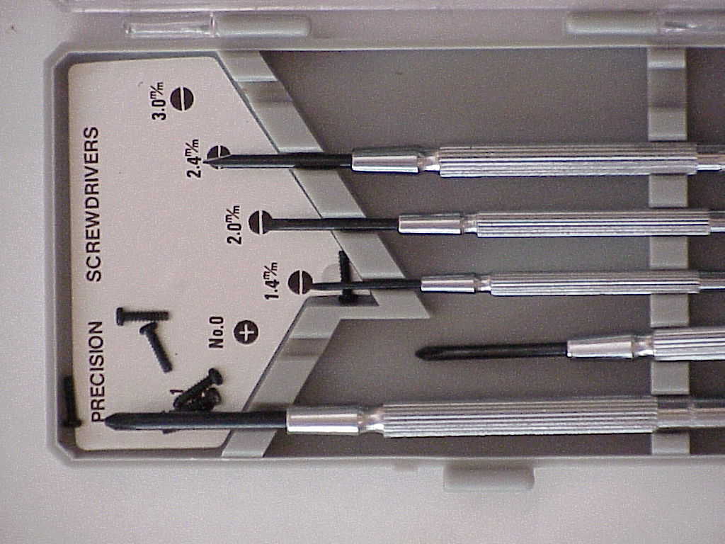
(Click for a larger view - warning, large picture) |
The Sidewinder is held together by 6 small phillips-head screws. I had to buy something called a "Number 0 Precision Screwdriver" from Walmart that came in a pack with 4 other small screwdrivers for about $3.25. The picture shows the case with the screwdriver I used to unscrew the screws retracted from its normal area. It also shows the small screws you must unscrew. |
| When all the screws are out the case opens easily. If you need to pull very hard at all then you have forgotten a screw. Once the case is open, take out the circuit board from the little plastic pillar type structures & loose the cord from the case. A plastic membrane will remain attached to the circuit board. Peel it off fairly gently. Disgard the case, the button membrane, the free buttons, etc. All you need is the cord & the board. You should now have the board removed from the casing as shown. | 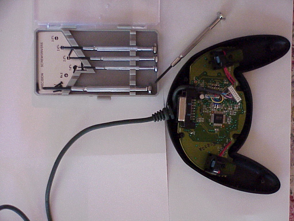
(Click for a larger view - warning, large picture) |
Step 2 - Clearing Out The Trigger Buttons
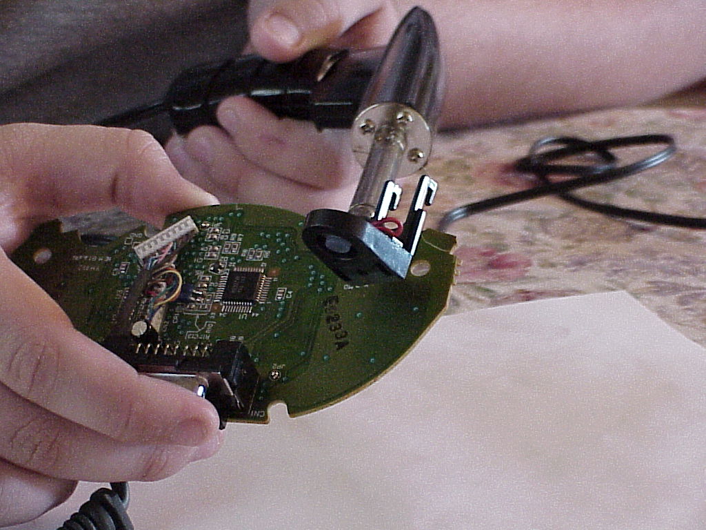
(Click for a larger view - warning, large picture) |
Slide the trigger mechanism off the circuit board as shown. |
| Follow the two red wires leading down to the board from each trigger. Heat the metal solder & pull genty on the wires from the back until the solder heats up & the wires come out. | 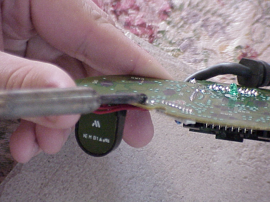
(Click for a larger view - warning, large picture) |
(Click for a larger view - warning, large picture) |
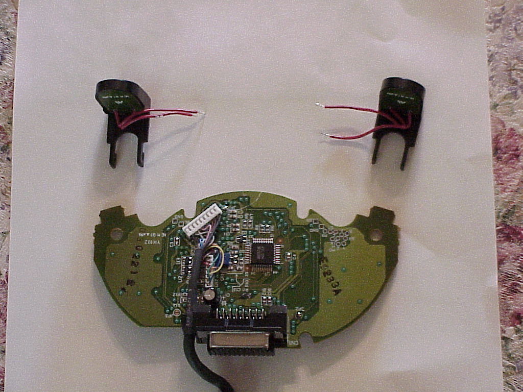
Do this to both triggers, remembering where the wires were placed. You may now throw away the trigger parts. The figure shows the board with both triggers detached. |
Step 3 - Two Inputs
Out of the Way
(Click for a larger view - warning, large picture) |
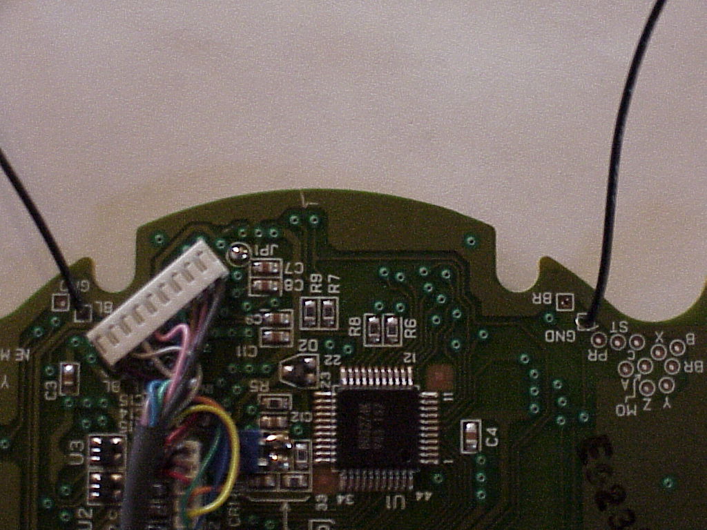
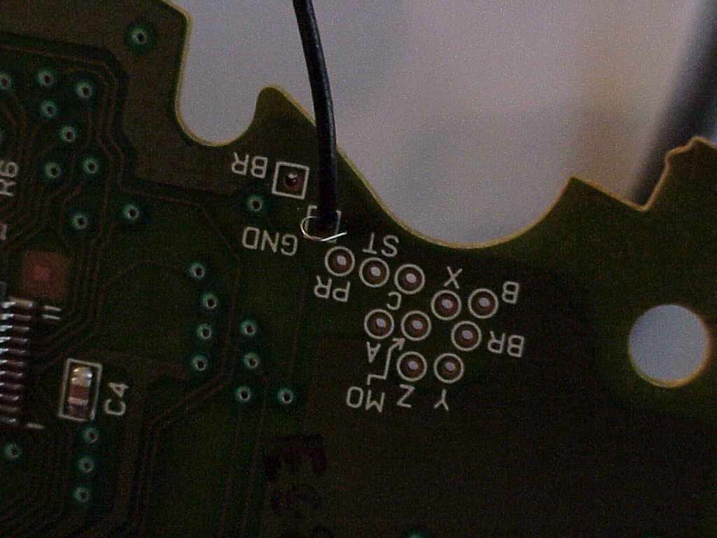
Each place you removed a trigger from had
either BL or BR written on it, along with one ground. Locate the
solder point labeled BR along the bottom of the board, not the one in the
mass of solder points nearby. Solder a wire to the ground wire, labeled
GND nearby. To do this strip the wire, probably with your teeth, and stick
it through to the other side before soldering. I used the wire type shown
here.
|
| The other trigger removed had two solder points, one labeled GND and the other BL, like that which is shown here. | 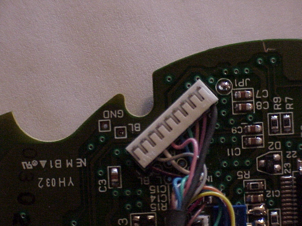
(Click for a larger view - warning, large picture) |
(Click for a larger view - warning, large picture) |
You will only solder to the point labled BL,
using the same technique as used above. Your board should now look like
this.
|
Step 4 - Soldering the Big Bunch of Inputs
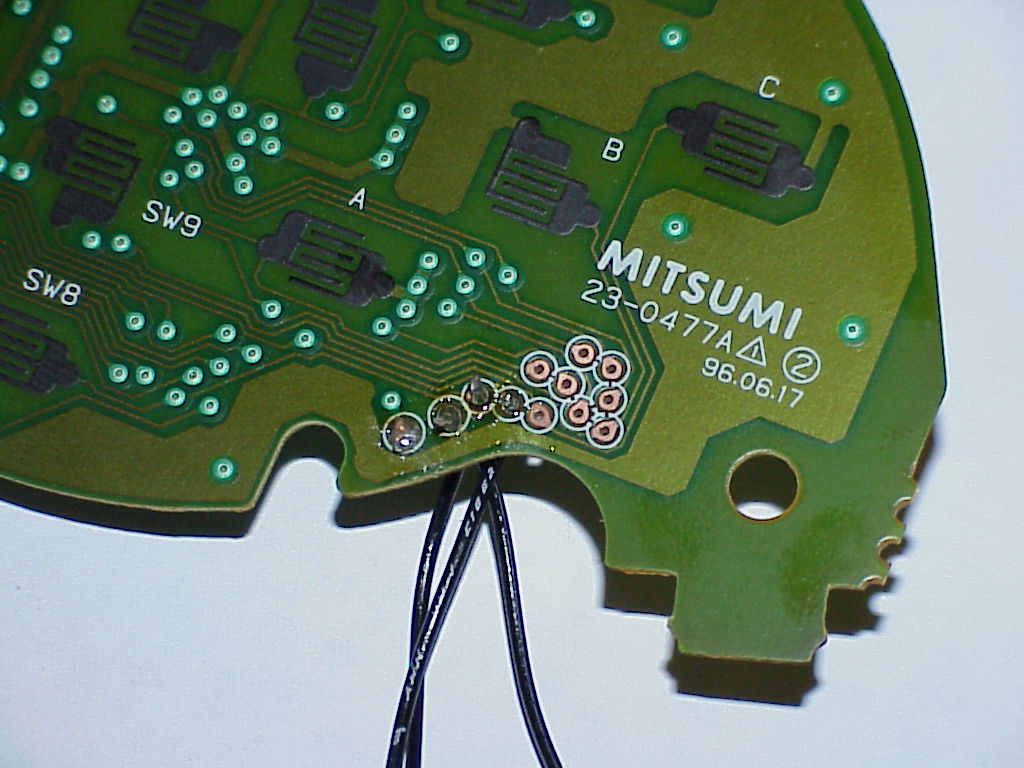
There is one large big bunch of inputs which
you should solder too, pictured at left. Solder to every point,
except the BR closest to the ground point. Be careful and use a small amount
of solder. Go in a pattern and be careful not to leave middle solder points
for last. See picture at right for an example.
(Click for a larger view - warning, large picture) |
(Click for a larger view - warning, large picture) |
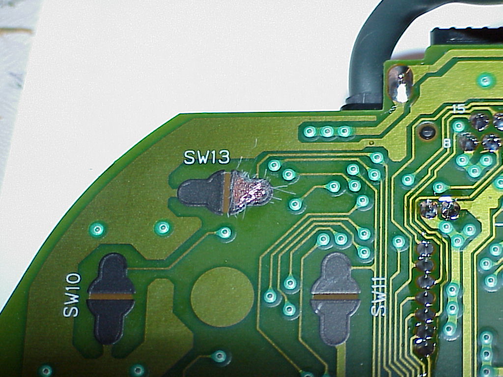
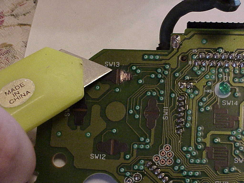
Step 5 - Directional Pad
Use a razor or box cutter as shown below to
scrape away as much plastic stuff as you can from each one of the black
contacts. Then go over the contact with the soldering iron. If you do not,
the covering melts when you attempt to solder for real. Now scratch again
to get the last of the gunk off and make sure to leave deep scratches to
help the solder adhear to the pad. The figure on the left is the contact
before being reheated, and on the right is the contact afterwords.
To solder, I found the best method was to drop a small bead of solder directly
onto the contact, and to later apply a wire and press on the wire with
the soldering iron.
(Click for a larger view - warning, large picture) |
(Click for a larger view - warning, large picture) |
Step 6 - Barrier
Strips and Beyond
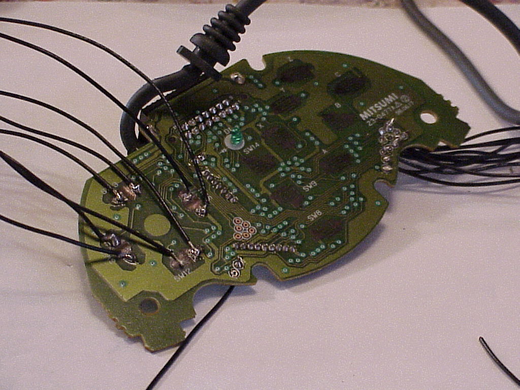
(Click for a larger view - warning, large picture) |
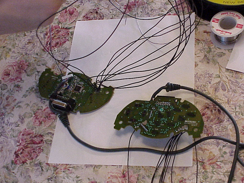
(Click for a larger view - warning, large picture) |
Your board should now resemble the two pictures above (where multiple joysticks at different levels of completion are shown). Bolt the whole assembly to wood and connect all the wires to screw down barrier strips. You will need about 24 sections per joystick. Connect your pad(s) to the computer and run the sidewinder test utility from control panel. Take the ground wire that used to be connected to a trigger & touch it to other wires. If the ground wire touches another ground wire nothing happens. If a ground wire touches a non-ground wire it signals a button press. Use what you know to map out which wires are which & record this information! Label each end of each barrier strip. Beware, the mode button only flashes on the controller when pressed, and not in the diagnostic utilities. The barrier strip lets you use the 5 ground inputs you have for each Sidewinder to branch out to each of your many controls. It also takes stress off your soldering. If a quick connect fails you can unscrew it and rescrew it in a second or two, and not have to worry about heating up the iron. BTW, Barrier Strips & Quick Connects cost about $12 total for each Sidewinder if you buy from Radio Shack. Make sure to order ahead as they dont carry many female quick connects in the small sizes or that many barrier strips all of the same kind.
I hope you found this information to be helpful!
![]()
An excellent writeup - many thanks StaticX!