![]()
 |
 |
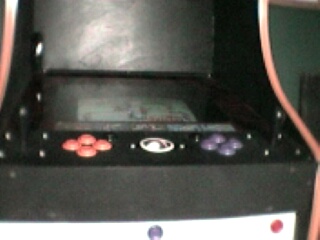
This is my quick and easy-no fuss way to mount a trackball. The Track ball I used is a Crystal Track ball from CompUSA. They're Cheap and they glow red and green.
I dont have figures for everything that I did because, well, I wrote this after I completed my project. This is so simple that Im sure most of you will give me a hard time about how easy this is.
![]()
Step One- Get a Crystal Trackball from CompUSA and Void your warranty by taking it apart. This is easy Its only the board and the ball.
(No picture)
![]()
|
|
 |
![]()
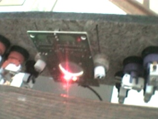
Ok you have your trackball apart and your ring from wherever. Now solder up your wires for your left and right buttons (This is easy - If your not sure which wire goes where, just get a couple of pieces of wire and and clip them to one of the three leads coming off the switch. Plug the mouse in and attach a clipwire to one of the remaining two leads. When you touch the two wire together and the diodes on the trackball turn from red to green you've got your man.)
So you have your wires soldered, your trackball apart and you have decided where to mount your trackball.
The board for the track ball is about 5 long and 3 ½ inches wide. The ball rests on the rollers for the PCBs.
You have a couple of choices now - you can drill the hole for the ball and then on the underside of the control panel route out around the hole to provide the reveal you want (how much of the ball sticks out on the control panel) . . .
NOTE THAT ALL FIGURES ARE NOT TO SCALE
This is NOT the method I chose, for one I dont own a router even though they are relativly cheap to buy they get yah on those router bits. The bits can cost forty bucks and up. A little steep for a one time thing.
So what I did was simple and painless. I took my drill and I cut slots out for the wheels of my pcbs to turn freely.
These only need to be about ¾ long and a ¼ deep. I accomplish this with a big drill bit and a file. I drilled 4 holes as close together as possible and then filed out the channel. After you have your channels in you may have to chip and dig at these channels a little more once you assemble everything.
![]()
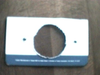
Now Drill two holes about 2 ½ from the Center of the trackball hole.
My figure doesnt really show but the holes should be in a straight line.
![]()
 |
|
![]()
|
|
(Note the two White pieces of plastic are and were only temporary) |
![]()
 |
|
![]()
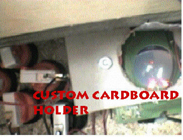
I know some of you are saying cardboard? Trust me - I have a 10 year old nephew and an 8 year old niece who BEAT this trackball and I swear it works great.
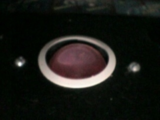
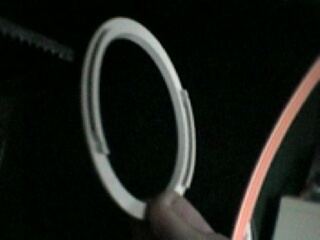
Oh, dont forget to put your ring on (figure 1) and your all done.
Good luck and if you have any questions e-mail me.
![]()
Excellent! Thanks Ray!